Why is the RS-232 not working right?
PIC serial communication tutorial. RS232 uses voltages below (-5V)to represent a logical level '1', and voltages above (5V)to represent a logical level '0'. Therefore, to use this protocol we need voltage level conversion. This is possible using the device such as the MAX232. May 03, 2012 I have a PIC 16F887A connected to the serial port. I want it to lit a green led when it receives 0x01 and lit a red led when it receives 0x00 from pc. I send the characters from a C# windows forms application, the PIC itself is programmed with CCS C. Tutorial para usar la comunicacion serial en los microcontroladores PIC con el compilador CCs.

- The PIC® MCU is Sending Garbage Characters.
- Check the clock on the target for accuracy. Crystals are usually not a problem but RC oscillators can cause trouble with RS-232. Make sure the #USE DELAY matches the actual clock frequency.
- Make sure the PC (or other host) has the correct baud and parity setting.
- Check the level conversion. When using a driver/receiver chip, such as the MAX 232, do not use INVERT when making direct connections with resistors and/or diodes. You probably need the INVERT option in the #USE RS232.
- Remember that PUTC(6) will send an ASCII 6 to the PC and this may not be a visible character. PUTC('A') will output a visible character A.
- The PIC® MCU is Receiving Garbage Characters.
- Check all of the above.
- Nothing is Being Sent.
- Make sure that the tri-state registers are correct. The mode (standard, fast, fixed) used will be whatever the mode is when the #USE RS232 is encountered. Staying with the default STANDARD mode is safest.
- Use the following main() for testing:
Check the XMIT pin for activity with a logic probe, scope or whatever you can. If you can look at it with a scope, check the bit time (it should be 1/BAUD). Check again after the level converter.
- Nothing is being received. First be sure the PIC® MCU can send data. Use the following main() for testing: When connected to a PC typing A should show B echoed back. If nothing is seen coming back (except the initial 'Start'), check the RCV pin on the PIC® MCU with a logic probe. You should see a HIGH state and when a key is pressed at the PC, a pulse to low. Trace back to find out where it is lost.
- The PIC® MCU is always receiving data via RS-232 even when none is being sent.
- Check that the INVERT option in the USE RS232 is right for your level converter. If the RCV pin is HIGH when no data is being sent, you should NOT use INVERT. If the pin is low when no data is being sent, you need to use INVERT.
- Check that the pin is stable at HIGH or LOW in accordance with A above when no data is being sent.
- When using PORT A with a device that supports the SETUP_PORT_A function make sure the port is set to digital inputs. This is not the default. The same is true for devices with a comparator on PORT A.
- Compiler reports INVALID BAUD RATE.
- When using a software RS232 (no built-in UART), the clock cannot be really slow when fast baud rates are used and cannot be really fast with slow baud rates. Experiment with the clock/baud rate values to find your limits.
- When using the built-in UART, the requested baud rate must be within 3% of a rate that can be achieved for no error to occur. Some parts have internal bugs with BRGH set to 1 and the compiler will not use this unless you specify BRGH1OK in the #USE RS232 directive.
This is a small example shows how to use PIC16F877A UART module using CCS PIC C compiler.
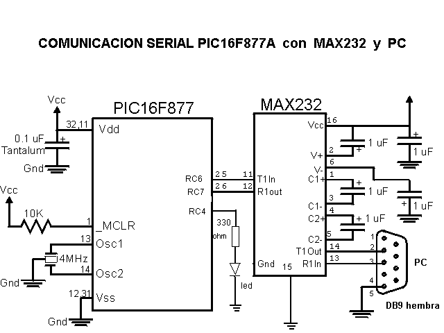
PIC16F877A UART connection circuit schematic:
Pin RC6 (TX) and pin RC7 (RX) are used for the UART (serial) communication between the microcontroller and the computer. To change between TTL logic levels (5V) and RS232 signals (+/-12V), an IC is needed which is max232.
Don’t connect TX and RX pins directly to an RS232 serial port which may damage your microcontroller.
CCS C compiler serial monitor can be used to communicate with the microcontroller.


PIC16F877A UART example CCS C code:
This is the full C code for this example.
